Kinetis E and OpenOCD update, and some Kinetis FTMRH flasher code and JTAG rambling
Following up on my last post, I managed to get OpenOCD flashing a Kinetis MKE02Z64VLD2 chip, to the point that I could hook it up to Kinetis Design Studio and program/debug almost as easily as with my J-Link, albeit without unlimited flash breakpoints, and it would often get confused about where it was on startup, although after hitting F8 everything would come back to normal.
I posted to the OpenOCD-devel mailing list and got a bunch of responses from others who had been working on the same problem, including Ivan Meleca, who had written a flash driver for the KE02/4/6 series but hadn't had time to upload it. I tested this out tonight on my MKE02Z64VLD2 and MKE04Z8VTG4 boards and it works well, so look forward to seeing that in mainline OpenOCD soon.
Ivan's code works, so I don't want to mess with it, but I'm proud of a couple of little tricks I figured out for my own implementation. I wrote a Python script to process the output of arm-none-eabi-gcc -g -O0 -mcpu=cortex-m0plus -mthumb -c -Wa,-adhln, extract out the opcodes, and comment everything up nicely, which lets you build self-contained routines that are easy to download and run on target devices. I'm not sure how everybody else wrote their flasher code, but they all seem to have ended up with slightly differently formatted hex bytes embedded in C files, so maybe by hand? Anyway, my flash algorithms and C-to-assembly-to-C code are up on GitHub as myelin-mcu-flash.
Next, my esp8266-jtag boards came back from OSHPark, and I soldered one up and connected it to my LPC-Link2, only to find that OpenOCD doesn't support JTAG operations on CMSIS-DAP adapters, only SWD. So I started writing some code to get that working. The next day, someone wrote on OpenOCD-devel that they were trying to do the same thing. So hopefully we can combine efforts and sort it out. I've learned a lot about JTAG in the last few days -- in a nutshell it's a very complicated way to reset a chip and read and write two registers, but it turns out that you can do a *lot* with those building blocks :)
Here are some notes from my attempts to get OpenOCD to support the raw JTAG operations in the CMSIS-DAP API, to talk to my ESP8266 board.
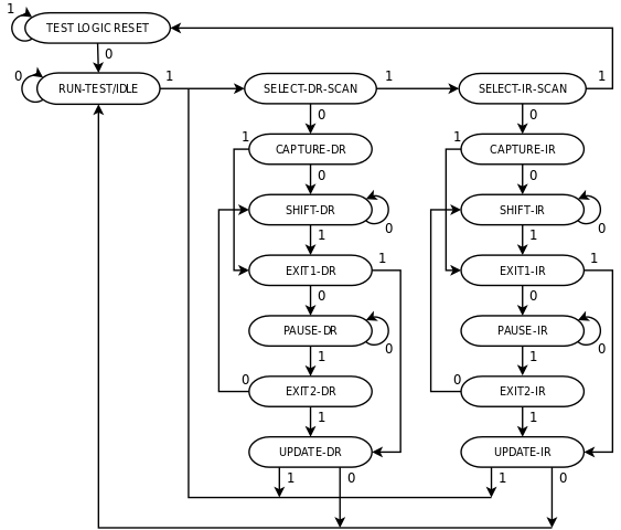
To get JTAG to work, you need to be able to clock in arbitrary sequences on the TMS pin, and you need to be able to clock in arbitrary sequences on the TDI pin with TMS low, while capturing output on the TDO pin, and setting TMS high as you clock in the final bit. This makes more sense if you look at the JTAG state diagram. TEST LOGIC RESET resets the test logic. Entering CAPTURE-DR copies data from the device into the DR register, and entering UPDATE-DR copies data from the register to the device. Every entry into SHIFT-DR clocks a bit from TDI into DR (on the rising edge of TCK), and a bit from DR out TDO (on the falling TCK edge). CAPTURE-IR, SHIFT-IR, and UPDATE-IR work similarly. All other states are just intermediaries that make it convenient to navigate around the state machine without needing too long of a sequence on TMS.
The relevant CMSIS-DAP operations, using the defines in the mbed CMSIS-DAP code:
ID_DAP_SWJ_Sequence, which clocks out a sequence on TMSID_DAP_JTAG_Sequence, which clocks out sequences on TDI, and optionally sets TMS and captures TDO.
DAP_SWJ_Sequence is already supported, because it's necessary to switch between JTAG and SWD mode. ID_DAP_JTAG_Sequence isn't used for SWD, but we need it for raw JTAG. The packet format seems to be:
- byte 0: the number of TDI bit sequences in the packet
- byte 1: sequence info for the first sequence
- byte 2..length(sequence 1): sequence data for the first sequence
- ... other sequences follow ...
The max sequence length is 8 bytes (64 bits), and the sequence info byte is: (0x80 if capturing TDO, else 0) | (0x40 if TMS is set, else 0) | (sequence length in bits, with 64 encoded as 0).
This suggests that a 'scan' operation (writing something into the IR or DR register) will require one DAP_SWJ_Sequence command to move the TAP to Shift_IR or Shift_DR and one DAP_JTAG_Sequence command to write the command. We can probably just leave the TAP in the shift state once the command is done, but we could use another DAP_SWJ_Sequence to get back to the idle state if that's not okay.
Looking at the bitbang driver, it looks like the desired end state is given in cmd->cmd.scan->end_state, the input and type (input or output) can be obtained via jtag_build_buffer and jtag_scan_type, and it's an IR scan if cmd->cmd.scan->ir_scan is set. The actual scan function moves to the TAP_DRSHIFT or TAP_IRSHIFT state as required, then clocks the data in/out on TDI/TDO, then executes another state_move to get to the desired end state. So I guess we'll actually require three DAP operations to do this, because of the final requirements for TMS (unless we want to try to pack those into the JTAG_Sequence packet).
11pm update: Implemented! It compiles, but I haven't tested it at all yet, so expect many bugs..