Debugging the ESP8266 with JTAG -- breakout board with an SWD-style JTAG connector
I found out a few days ago that it's possible to debug the ESP8266 using JTAG (and the Xtensa-specific xt-ocd, or the open source OpenOCD). It looks like work to make this possible has been going on for about a year now, as well as related work to develop UART-based GDB stubs (there's now an official one!).
This doesn't seem to have attracted nearly as much attention as I would have thought. Maybe because hobbyists nowadays are used to the Arduino platform, which doesn't include any on-chip debugging support? (Unless you cut some traces and plug in an Atmel ICE unit.) The ubiquitous availability of on-chip debugging is probably my favourite thing about working with ARM Cortex-M chips; it's kinda painful to go back to an environment where I don't have access to that. I'm currently working on some DMX512 hardware, and recently had a yak-shaving-like need to implement my own non-blocking software UART; this wouldn't have been possible without being able to breakpoint and single-step using KDS, SWD, my J-Link, and my Saleae Logic 8.
Anyway, I'm super excited to give this a try on an ESP8266. Unfortunately all my ESP-03 modules are soldered into boards that tie GPIO15/MTDO to ground, and otherwise I only have a couple of ESP-01 units, which don't bring out the JTAG pins.
So... time to get an ESP-12 or two, and whip up a board with all the bits and pieces JTAG requires!
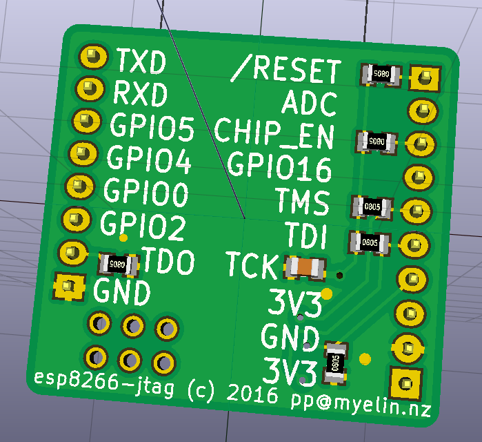
JTAG is an old interface/protocol, and is designed to daisy chain through a bunch of chips, so it has much more in the way of pullup/pulldown requirements than SWD. Here's what I ended up putting on my board:
- Pulldown on TDO. This should really be a pullup, except that TDO/GPIO15 is part of the boot_sel combo (GPIO15:GPIO0:GPIO2), which has to be 011 to boot from flash, so GPIO15 must be pulled low if you ever want to boot without an attached debugger.
- Pulldown on TCK. This is also nonstandard; most JTAG diagrams show no pull resistors on TCK, but have it terminated with 68R and 100pF in series to ground. ARM recommends a pulldown, though -- to avoid spurious clock edges during hot-plugging -- so I'm going with that.
- Pullups on TDI and TMS. This is standard JTAG.
- Pullups on CHIP_EN and /RESET -- always required on the ESP8266.
I chose to use an SWD-style 2x5 1.27mm connector, which will hopefully let me connect this to my J-Link using the same cable that I use for ARM debugging. Here's how the board looks:
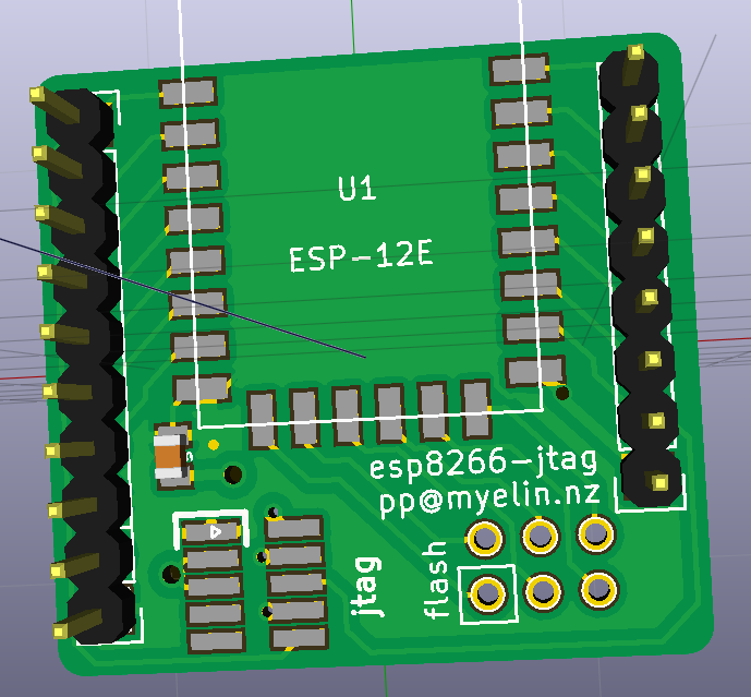
Sending this off to OSHPark shortly! Design files and most recent gerbers are on GitHub.